
Drilling and Casing the Wellbore
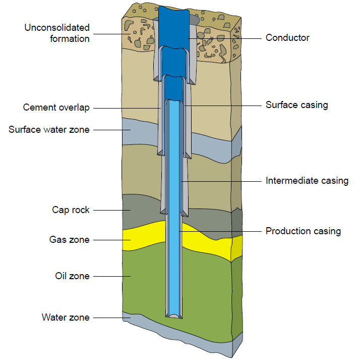 |
| Drilling and Casing the wellbore - figure 1 |
Prior to a well being ‘spudded in’, a conductor (large casing) is placed in the surface formation to provide a starting point for drilling operations. On land wells, a cellar may be constructed and the conductor driven into the ground with a pile driver. Alternately, a post hole type boring rig may be used to make a hole in which the conductor can be cemented. On offshore wells, the conductor is typically installed in slots designed into the platform structure. The well is drilled in stages and cased to prevent hole collapse and the movement of formation fluids into the wellbore. The number and size of casings is determined by the final well depth, formation conditions and final well pressure and service (oil or gas, single or dual, etc.).
The diagram in Figure 1-1 Drilling and Casing the Welbore shows a typical three-casing onshore well. With each casing string being cemented in place, the formation conditions and well location determine how much cement overlap is
applied in each casing string. A good cement bond between the formation and casing is essential to prevent the migration of fluids between the producing zones or to the surface. This can be checked or confirmed by running a CBL (Cement Bond Log) run on electric line before continuing with the next stage of drilling and completing the well.
applied in each casing string. A good cement bond between the formation and casing is essential to prevent the migration of fluids between the producing zones or to the surface. This can be checked or confirmed by running a CBL (Cement Bond Log) run on electric line before continuing with the next stage of drilling and completing the well.
[post_ad]
Care is taken at all phases of drilling to ensure that the surface facilities are isolated from the downhole formation pressures. This is achieved by the density of the drilling mud (creating hydrostatic pressure in the wellbore to balance formation pressure) and the use of blowout preventers (BOP). The BOP stack is mounted immediately below the rig floor on land wells and jack-up rigs. On semisubmersible rigs and subsea completions, the BOP stack is mounted on a template on the seabed.
The wellbore is drilled to a depth just below the area of strata where the oil or gas is trapped. This area is known as the reservoir formation and is usually a layer of sand, shale or rock, which contains the gas or oil. The thickness of the reservoir can vary from only a few feet to several hundred feet or even several thousand feet in prolific fields.
To allow the reservoir fluids, i.e., oil and gas, to enter the wellbore, perforations are made through the casing within the reservoir interval. The perforating gun is generally lowered into the wellbore on electric wireline. Alternately tubing conveyed perforating systems permit the running of the perforating explosives with the production tubing string. After confirming proper placement, the perforating gun is fired electrically from the surface or in the case of TCP, a drop bar may be used to detonate the guns.
When the perforating gun is fired, a perforation tunnel is created through the casing and cement sheath and into the reservoir formation. This provides clear channels through which the oil and gas can enter the casing, where it is produced to surface through the production tubing. During the completion phase of a well, the production tubing and packer are installed. Production tubing is a smaller diameter pipe, which is lowered inside the casing to a point somewhere above the perforations. Attached to the lower end of the tubing, is the production packer.
The packer incorporates slips (teeth) to secure the packer in place and one or more sealing elements to provide hydraulic isolation. With the tubing and packer are at the desired depth, the slips and the rubber seal elements on the packer are activated, usually either by rotating the tubing or by applying hydraulic
pressure through the tubing bore. This causes the slips on the packer to expand and bite into the casing and also causes the rubber seal elements of the packer to expand and seal off against the internal diameter of the casing. With the packer anchored in place, the gas and oil enters the casing through the
perforations and flows up to the packer, where it enters the production tubing and flows to surface.
The tubing-casing annulus is the space between the outside diameter of the tubing and the inside diameter of the casing above the packer. This space is generally filled with fluid, such as water or brine containing a corrosion inhibitor, to protect the tubing and casing from corrosion. The hydrostatic pressure (weight) of the annulus fluid tends to hold the packer in place and also provides a means of killing the well, when necessary, by admitting the annular fluid into the tubing string.
Some wells are constructed with a liner. This option requires a smaller hole and does not require a casing string to run all the way to the surface, representing a significant cost saving in drilling time and casing costs. The liner hanger system supports the liner off the bottom of the well until the cementing operation is completed. Liner hangers can also be installed when an existing well is worked over and the depth increased.
Drilling and Casing the Wellbore
 Reviewed by Industri Migas
on
9:11 PM
Rating:
Reviewed by Industri Migas
on
9:11 PM
Rating:
Reviewed by Industri Migas
on
9:11 PM
Rating:
Industri Migas

Established in 2012, Industrimigas.com stands as the premier Indonesian blog dedicated to the Oil and Gas Industry. As a trailblazer in the field, Industrimigas.com delivers up-to-the-minute news, comprehensive industry insights, career opportunities, a directory of companies, data on offshore rigs, an equipment marketplace, and much more.


Hi there
ReplyDeletejust now i read your blog. its very Intresting. very well defining about the drilling and casing the wellbore. it will definitely help with us. thanks for sharing with us. well done. keep sharing.
DIC OIL TOOLS
https://dic-oiltools.com/tubing-casing.php
When you’re drilling, the bit will become clogged with material. To avoid the drill it from becoming clogged, it’s important to remove this stuff on a regular basis. Use a brush or compressed air. a basin wrench
ReplyDelete